Converting a Ham IV rotator to computer control
 My old Ham-IV rotator has been in storage for a while, but I’m keen on using it again for satellite tracking. Following moving object such as satellites across the sky requires computer control, so I decided to retrofit the Ham-IV’s controller box. After all the rotator controller box is just 3 switches and a position sensing pot, it shouldn’t be too hard to control using a microcontroller.
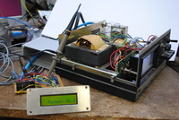
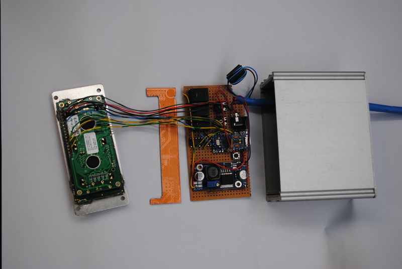
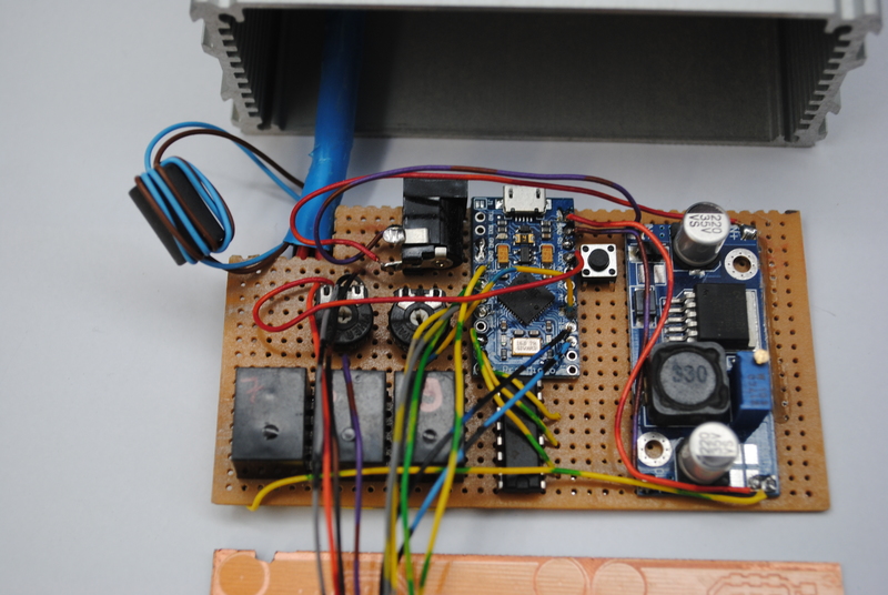
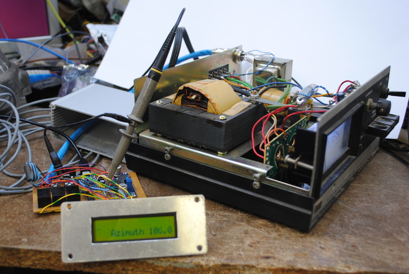
There is an excellent project by Anthony Good K3NG around for adding computer control to rotators. Since it makes no sense re-inventing the wheel, I used his code and built my own custom hardware. It consist of a small 5V power supply, an Arduino Pro Micro clone, a ULN2003A driving 3 relays, 2 pots and an LCD.
Reading the heading
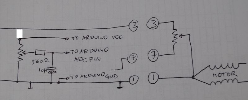
The most difficult part of the project was reading the position of the rotor. The Ham IV has a potmeter which is configured as a rheostat, with the pot wiper connected to ground. This puts a voltage on pin 3 on the back of the controller box which is proportional to the rotator’s position. It doesn’t have the correct voltage so a 1k potmeter is used to tap off a 0 to 5V voltage which can be fed into one of the Arduino’s ADC pins.
The potmeter is connected with one side to pin 3 of the controller box, the other side to pin 1 (ground). The wiper is connected to the ADC pin of the Arduino. I added a low pass filter as well to filter out some ripple on the position sensing circuit, after all this is a sensitive voltage going over a low cable run in an RF-rich environment.
Hardware definition
The rotator_pins.h file describes which Arduino pins control which function. Make sure to change them to reflect your implementation. Here’s mine:
#define rotate_cw 8              // goes high to activate rotator R (CW) rotation - pin 1 on Yaesu connector
#define rotate_ccw 9             // goes high to activate rotator L (CCW) rotation - pin 2 on Yaesu connector
#define brake_az 7               // goes high to disengage azimuth brake (set to 0 to disable)
#define blink_led 17
#define rotator_analog_az A0     // reads analog azimuth voltage from rotator - pin 4 on Yaesu connector

//classic 4 bit LCD pins
#define lcd_4_bit_rs_pin 15
#define lcd_4_bit_enable_pin 14
#define lcd_4_bit_d4_pin 5
#define lcd_4_bit_d5_pin 4
#define lcd_4_bit_d6_pin 3
#define lcd_4_bit_d7_pin 2
LCD connections
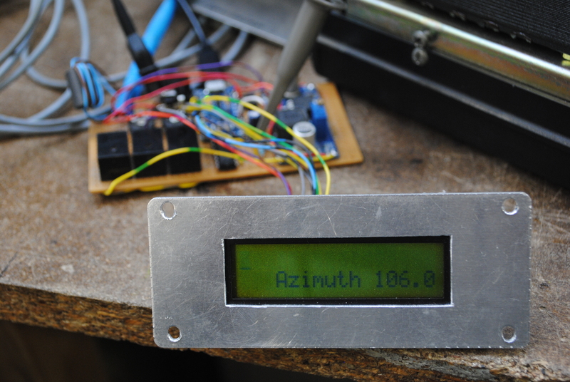
I connected the LCD to the Arduino using coloured wires. Here’s the connection diagram:
- LCD pin 1 (ground), gray/black, to ground
- LCD pin 2 (VCC), orange/red, to VCC
- LCD pin 3 (contrast pot), purple/brown, to contrast pot wiper, 10K between VCC and GND
- LCD pin 4 (RS), Arduino pin 15, black/blue
- LCD pin 5 (RW), black/brown, to ground
- LCD pin 6 (E), Arduino pin 14, blue/black
- LCD pin 11 (D4), Arduino pin 5, gray/yellow
- LCD pin 12 (D5), Arduino pin 4, yellow/gray
- LCD pin 13 (D6), Arduino pin 3, green/yellow
- LCD pin 14 (D7), Arduino pin 2, yellow/green
Define the features
The rotator_features.h files allows choosing which features to include. The Arduino Pro Micro doesn’t have sufficient code space to enable all features so I had to disable some. Here’s what I have enabled:
#define FEATURE_YAESU_EMULATION           // uncomment this for Yaesu GS-232 emulation on control port
#define LANGUAGE_ENGLISH         // all languages customized in rotator_language.h

/* position sensors - pick one for azimuth and one for elevation if using an az/el rotator */
#define FEATURE_AZ_POSITION_POTENTIOMETER   //this is used for both a voltage from a rotator control or a homebrew rotator with a potentiometer
                                // All displays require k3ngdisplay.h and k3ngdisplay.cpp in the ino directory!
#define FEATURE_4_BIT_LCD_DISPLAY // Uncomment for classic 4 bit LCD display (most common)
Calibrating the heading
Hardware calibration
To calibrate the potmeter voltage read by the ADC, load a sketch into the Arduino that continuously sends the ADC value to a serial terminal, such as this one.
First calibrate the original controller box using the potmeter next to the dial. Now manually rotate the rotator to the full CW position (gives maximum voltage on pin 3 of the controller box) and measure the voltage on the ADC pin. Adjust the potmeter so that the voltage in the Arduino’s ADC pin is slightly under 5V. Now note the ADC value at this voltage. Going a bit over 5V crashes the Arduino, going a lot over 5V damages it. Adding a 5.1V zener across the Arduino’s ADC pin is a good idea.
Now rotate all the way CCW, and note the ADC value. These 2 values need to be entered into the rotator_settings.h file. These are my settings.
#define ANALOG_AZ_FULL_CCW 17
#define ANALOG_AZ_FULL_CW 1010
The more of the ADC’s range is used, the more accurate the position sensing will be. So try to get the CCW value as close to 0 and the CW value as closed to 1024 as possible.
Software calibration
Then proceed to do the software calibration as per the wiki page, section 500 Heading Calibration.
_On the serial interface, issue the O command and manually rotate the rotator to full counter-clockwise 180 degrees and send a carriage return. Then issue the F command and manually rotate the rotator to full clockwise (270 degrees on a 450 degree rotator, or 180 degrees on a 360 degree rotator) and send a carriage return.
The calibration settings are written to non-volatile EEPROM memory._
Controlling the motor and brake
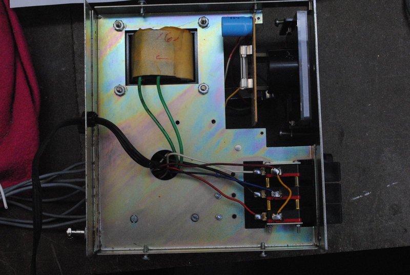
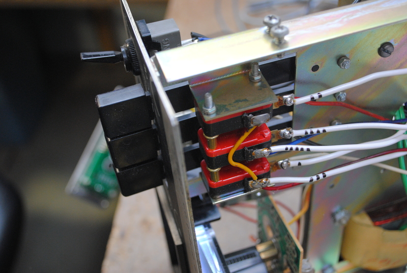
Controlling the motor is easy. The Arduino controls 3 relays (through a ULN2003A driver), which emulate the CW, brake and CCW switches in the original controller box. If you look under the lever switches you’ll see 3 mechanical switches; I just wired 3 relays in parallel with these switches.
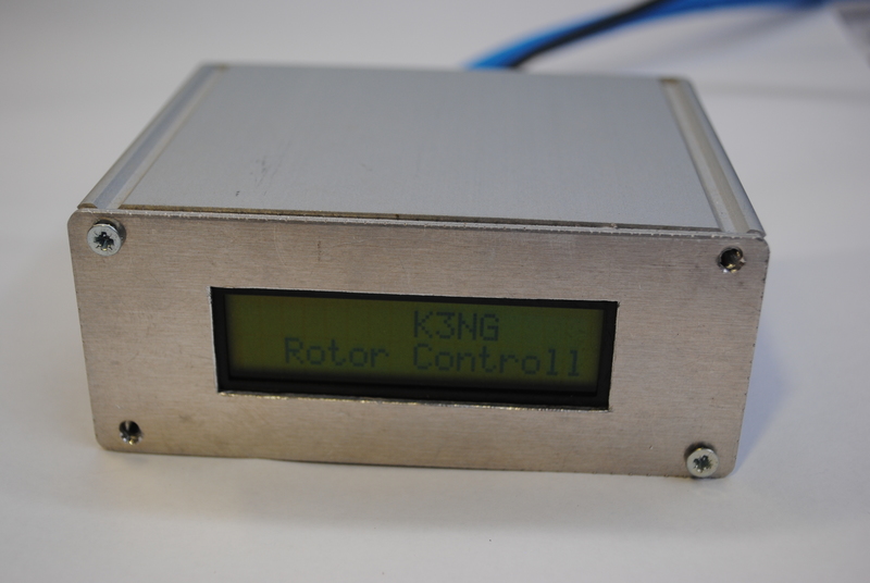
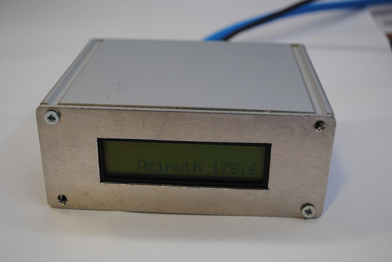
Case
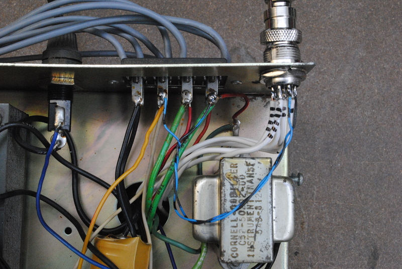
I built the controller board into a small Hammond case which will sit nicely on top of the original controller box. On the front is a cut-out for the LCD, the back has a barrel jack connector for the power supply and a cable coming out to connect to the rotator box. In the back panel of the rotator box I mounted a 8-way Kenwood-style socket which bring the following connections out to the controller box:
- pin 1: CCW switch (white wire marked 3) - (connects to pin 6 on the original control box connector)
- pin 2: CW switch (white wire marked 2) - (connects to pin 5 on the original control box connector)
- pin 3: CW/CCW switch common (black wire) - (connects to pin 2 on the original control box connector)
- pin 4: brake switch (white wire marked 1)
- pin 5: brake switch common (black wire)
- pin 6: position pot (blue wire) - (connects to pin 3 on the original control box connector)
- pin 7: position pot (ground) (brown wire) - (connects to pin 1 on the original control box connector)
- pin 8: N/C
Debugging and tweaks
Compilation issue with &Serial
The Arduino Pro Micro identifies the USB serial emulation as Serial, the compiler didn’t like the way K3NG’s firmware maps this variable using a pointer so I searched-and-replaced all control_port->-statements by Serial and then it compiles.
#define CONTROL_PORT_MAPPED_TO &Serial // change this line to map the control port to a different serial port (Serial1, Serial2, etc.) control_port = CONTROL_PORT_MAPPED_TO; control_port->begin(CONTROL_PORT_BAUD_RATE);
Azimuth jitter
I found there is a 180mV ripple on the position pot voltage which cause azimuth readings to jump around. It was resolved by increasing the AZIMUTH_SMOOTHING_FACTOR in rotator_settings.h to 70. This effectively low-pass filters the read azimuth value in software.
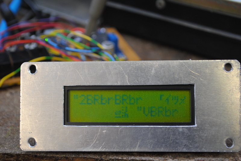
Snubber network
I had issues with inductive spikes from the motors messing with the LCD. After the motor starts turning, the LCD would show all garbled text.
Eric Schumacher left the following comment on the Radio Artisans Yahoo group: Make sure that the LCD module ground goes directly to an Arduino ground pin and does not share the pin. Connect a snubber (0.1uf ceramic in series with 10 ohms) across each of the motor relay contacts. Ideally the motor power will not share a common with the Arduino.
Obviously I can’t isolate the controller box ground from the motor ground (pin 1) because of the way I am reading the azimuth position pot. I will try adding snubbers.
Yeasu test commands
The interface emulates a Yeasu GS-232 compatible rotator. The following commands can be used to test the rotator controller when connecting to it through the serial interface (baudrate = 9600). When you send a CR (enter) the firmware will reply with a ?> prompt.
R Clockwise Rotation
L Counter Clockwise Rotation
Starts rotation - you should hear the relay click.
A CW/CCW Rotation Stop
S All Stop
Stops rotation - you should hear the relay click.
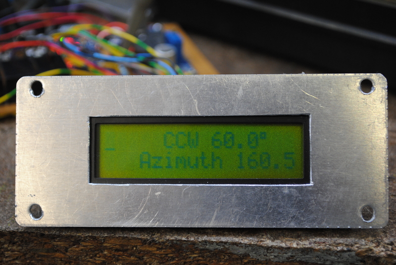
C Antenna Direction Value
Returns the current antenna position, e.g. AZ=275.
Mxxx
Move to azimuth position xxx, e.g. _M090.
See Yeasu GS-232 Commands or the Yeasu GS-232B Manual.
Computer control using Gpredict on Ubuntu
Rotctl
Rotctl is a daemon which interfaces with the rotator controller over serial.
Install:
sudo apt-get install libhamlib-utils
Find Arduino serial port:
root@ubuntu:# ls /dev/serial/by-id
*usb-SparkFun_SparkFun_Pro_Micro-if00 *
Start rotctl:
rotctl --model=601 --serial-speed=9600 --rot-file=usb-SparkFun_SparkFun_Pro_Micro-if00
Test rotctl:
Rotator command: P
Azimuth: 100
Elevation: 0

Rotator command: S
Start rotctl daemon:
rotctld --model=601 --serial-speed=9600 --rot-file=usb-SparkFun_SparkFun_Pro_Micro-if00
Configure Gpredict
Preferences :: Interfaces :: Rotators
- Host: localhost
- Port: 4533
- Az type: 0 -> 180 -> 360
- Min Az/El: 0
- Max Az: 360
- Max El: 90
More pictures
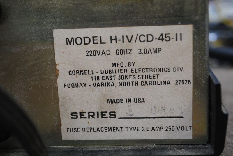
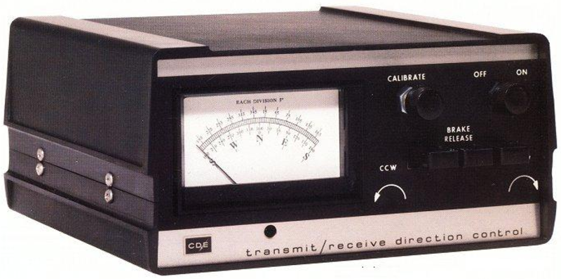
MODEL H-IV/CD-45-II, 1 JUN 81 vintage :-)
Links
- Hy-Gain HAM-IV Rotator Upgrade - uses PICAXE controller but has good info on modifying the original HAM-IV control box
- Radio Artisan Yahoo Group
- k3ng_rotator_controller source code on Github
- k3ng_rotator_controller wiki on Github